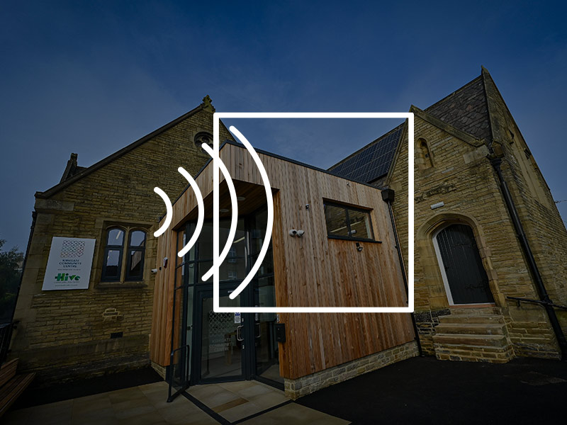
Acoustic Consultancy and Design for Breeam HEA05 and POL05.
Acoustic Consultancy, Sound Testing & Environmental Monitoring in Birmingham
NOVA Acoustics Ltd delivers comprehensive acoustic consultancy and UKAS-accredited sound insulation testing across Birmingham, the West Midlands, Staffordshire, Shropshire, Herefordshire, Worcestershire, Warwickshire, Oxfordshire, and Oxford.
With expert engineers and local presence, we respond quickly to your project needs, offering tailored acoustic and environmental services that meet both regulatory requirements and commercial goals.
Acoustic Consultancy Services
We support planning, development, design, and compliance needs across various sectors. Our team has deep knowledge of local authority requirements across Birmingham, Leicester, Oxford, and surrounding counties.
Services Include:
• BS 4142 & BS 8233 Noise Impact Assessments
• Residential & Commercial Noise Surveys
• Construction Noise & Vibration Monitoring (BS 5228)
• Building & Room Acoustic Design
• MCS 020 Heat Pump Assessments
• Environmental Permit Noise Impact Assessments
• Acoustic Enclosure Design
• Festival & Event Noise Monitoring
• Expert Witness Support
• 3D Noise Mapping & Modelling
UKAS-Accredited Sound Insulation Testing (Part E Compliance)
We specialise in sound insulation testing to ensure compliance with Approved Document E of the Building Regulations. We provide reports suitable for Building Control Officers with fast, cost-effective service.
Available Across: Birmingham, West Midlands, Leicester, Oxford, and all surrounding counties listed above.
What We Offer:
• Airborne and impact sound insulation testing
• Pre-completion testing and certified reports
• Sound insulation design consultation
• Pre/post-installation testing for leasehold flooring upgrades
As a UKAS Accredited Testing Laboratory (No. 8568), we guarantee reliable and expert service tailored to the demands of each regional authority.
Leasehold Flooring Upgrades? Many residential leases restrict flooring alterations without proof of equivalent or better acoustic performance. We offer:
• Baseline acoustic testing
• Design consultation for flooring systems
• Post-installation testing and compliance documentation
Noise, Vibration & Dust Monitoring
We provide environmental monitoring solutions to construction, industrial, infrastructure, and event projects across the West Midlands and adjoining counties.
Applications Include:
• Construction and demolition
• Motorsport and live events
• Industrial developments
• Transport and infrastructure
Service Features:
• Real-time cloud dashboards
• Class 1 sound meters and vibration sensors
• Weather station integration
• SMS/email alert triggers
• Power via mains, battery, or solar
Options:
• Hire-only systems with automated reporting
• Fully managed services with installation, live alerts, and Local Authority liaison
Our consultants can manage Section 61 applications and monitoring strategies to keep your project compliant and on track.
Noise at Work Surveys
We deliver Noise at Work Surveys to ensure compliance with the Control of Noise at Work Regulations 2005 across workplaces in Birmingham, Oxford, Bristol, and beyond.
What’s Included:
• Personal noise exposure measurement (LEP,d)
• Zoning and control recommendations
• Hearing protection evaluation
• Reporting aligned with HSE standards
Our Institute of Acoustics-trained consultants offer on-site services with quick turnaround and actionable results.
Planning & Development Noise Surveys
Whether you’re developing residential sites, commercial buildings, or entertainment venues, we provide compliant and timely noise surveys.
Survey Types:
• Environmental Noise Surveys
• BS 8233 Residential Noise Assessments
• BS 4142 Industrial Noise Impact Assessments
• BS 5228 Construction Noise & Vibration Surveys
• BREEAM HEA 05 & POL 05 Surveys
All assessments use Class 1 calibrated equipment and follow industry best practices. Our consultants help fast-track approvals by providing clear reports and mitigation
Why Choose NOVA Acoustics?
Local for rapid site response
Affordable pricing tailored to each project’s scope and timeline
Sectors We Serve
At NOVA Acoustics Ltd, we deliver tailored acoustic consultancy and testing services across a wide range of sectors. With deep industry knowledge and a flexible, client-focused approach, we help projects of all sizes meet regulatory compliance and achieve optimal acoustic performance.

From new builds to multi-unit developments, we provide sound insulation testing, design advice, and planning support.


Client Testimonials
“I plucked this company out of the air and I am so glad I did. Jaime has been most helpful and produced a report within a short time scale. The service has been first class and I have absolutely no hesitation in recommending NOVA acoustics.”
– Arnot Wilson
“We commissioned NOVA to conduct a sound test at our new house. From the get go Adam was incredibly helpful and knowledgeable. It is rare to meet professionals like that, who also go above and beyond to help and guide you through the process.”
– Na’ama Zisser
“The engineer who conducted the testing was friendly, professional and incredibly thorough. Overall I would say that NOVA provided an outstanding service from start to finish and I would not hesitate to recommend them.”
– Joe Bentley
“Really pleased with the service received from NOVA Acoustics on a recent noise risk assessment of our production room. The engineer Tom was great throughout and the report was clear and has made managing our noise control measures simple and effective.”
– Daniel Pontin
“NOVA Acoustics have been beyond helpful. Super speedy response and excellent communication. The noise impact assessment has been completed at a very fair price, and I’m really happy I chose NOVA Acoustics for the job.”
– Kelly Creates
“I used NOVA for acoustic reports for a project I’m working on converting retail units to residential, they was prompt, informative and well priced. I wouldn’t hesitate to use them again.”
– Peter Goldthorpe
“We have used NOVA Acoustics for a sound testing for installation of a new floor. Tom the engineer was very thorough, prompt and professional.”
– Anna Jóga
“Ryan and his team were very professional, installing monitoring equipment regarding a proposed planning application. We can definitely recommend NOVA Acoustics Ltd.”
– Pauline Whittle
NOVA Acoustics Ltd Birmingham Service Area
Address: Izabella House, 24-26 Regent Pl, Birmingham B1 3NJ, United Kingdom
Phone Number: 0121 7980107
Email: birmingham@novaacoustics.co.uk
Our Service Coverage
Our mobile consultants and regional engineers allow us to serve projects across:
• Birmingham & West Midlands
• Staffordshire, Shropshire, Herefordshire, Worcestershire, Warwickshire
• Oxfordshire, Gloucestershire
With flexible scheduling, remote access tools, and deep local knowledge, we deliver excellent service no matter your project’s location or complexity.
FAQs
Do I need sound insulation testing to meet Building Regulations in Birmingham or Oxford?
Yes. If you’re developing new build or converted dwellings in areas like Birmingham, Oxford, or across the West Midlands, testing is required to comply with Approved Document E of the Building Regulations.
When should I schedule pre-completion sound insulation tests in Bristol or Gloucestershire?
Testing should be scheduled once internal finishes like plastering are complete and all doors/windows are installed, but before final decoration.
How much does sound insulation testing typically cost in Shropshire or Warwickshire?
Pricing varies depending on the number of tests and dwellings. We offer competitive regional rates through our local engineers.
Can you test flooring for leasehold compliance in places like Oxford or Bristol?
Yes. We provide pre- and post-installation testing for wooden or hard floors to help meet lease clause requirements.
What happens if I fail the sound insulation test in Worcestershire or Staffordshire?
We’ll provide a detailed failure response and recommend cost-effective design improvements for retesting.
Is noise and vibration monitoring mandatory for construction in central Birmingham or Oxfordshire?
It’s strongly advised—especially near schools, hospitals, or residential areas. Local authorities may also require it as part of Section 61 consent.
What does a Section 61 consent involve in cities like Bristol or Gloucester?
It’s a formal agreement with the local council that allows specific noisy construction works within agreed limits and times.
Can you install and manage monitoring equipment in remote areas like Shropshire or Herefordshire?
Absolutely. Our systems support battery and solar power, ideal for hard-to-access or rural sites.
What alerts and reports can I expect from your environmental monitoring systems?
Our cloud-based dashboards offer real-time data with SMS/email threshold alerts and automated daily/weekly reports.
Do you provide fully managed or hire-only environmental monitoring in Stoke or Warwickshire?
Both. We tailor packages depending on whether you need full consultancy support or just the equipment.
Do I need an acoustic assessment for planning permission in Oxfordshire or Gloucestershire?
Yes. If your development is near roads, railways, or industrial zones, local planning departments may require a BS4142 or BS8233 assessment.
Can you support plant noise impact assessments in mixed-use projects across Birmingham and Bristol?
Yes. We regularly conduct assessments for air-con units, chillers, generators, and more to ensure compliance with environmental health thresholds.
What makes your consultancy service unique for regional planning submissions?
We combine technical expertise with in-depth local knowledge of planning authorities across the Midlands and South West.
What is a BS8233 Residential Noise Survey and do I need it in Warwickshire or Bristol?
It evaluates internal noise levels in proposed housing developments near major roads or railways. Most local planning authorities now require it.
Where do you provide acoustic services and noise surveys?
We cover a wide region including: Birmingham & West Midlands, Staffordshire, Shropshire, Herefordshire, Worcestershire, Warwickshire, Gloucestershire and surrounding counties.
Do I need sound insulation testing for my development in Birmingham or the West Midlands?
Yes. Any new-build dwelling or residential conversion in Birmingham, Solihull, Wolverhampton, Dudley, Walsall, or the wider West Midlands requires Part E sound insulation testing before Building Control can sign off the development.
When should I schedule pre-completion sound tests in areas like Coventry or Worcester?
Testing should be carried out once floors, walls, ceilings, and doors are fully installed and the property is quiet. Most clients book testing in the final stages of construction.
How long does sound insulation testing take?
A standard set of airborne and impact tests typically takes 1–2 hours, depending on the number of separating walls and floors.
What happens if the property fails the sound insulation test?
We issue clear remedial recommendations, suggest practical improvements, and return for retesting to help you achieve compliance quickly.
Do you offer sound testing for leasehold flooring changes in Birmingham apartments?
Yes. We carry out baseline tests, recommend compliant flooring systems, and complete post-installation testing for Lease to Alter applications.
Do I need a noise survey for planning permission in Birmingham or surrounding areas?
If your development is near transport routes, nightlife, industrial estates, or dense urban centres, local authorities often require a BS8233 or BS4142 noise assessment to support planning approval.
What is a BS4142 industrial noise assessment and when is it required in the West Midlands?
BS4142 assessments evaluate the impact of industrial/commercial noise on nearby homes. They are commonly required in Birmingham, Coventry, Wolverhampton, and industrial corridors across the Midlands.
Can you support planning applications with acoustic design recommendations?
Yes. We provide façade design, glazing and ventilation specifications, internal acoustic build-ups, and mitigation strategies that satisfy planning officers and accelerate approvals.
Do you carry out MCS 020 noise assessments for heat pumps in Birmingham?
Yes. We complete MCS 020 external noise calculations for air-source heat pumps to ensure compliance with planning and permitted development conditions.
Can you provide 3D noise modelling and mapping for developments in the Midlands?
Absolutely. We produce 3D noise maps and predictive modelling for residential, commercial, industrial, and infrastructure schemes across the region.
Is noise and vibration monitoring required for construction sites in central Birmingham?
Often yes. Birmingham City Council and neighbouring authorities frequently request monitoring for large or sensitive developments, especially near occupied properties or city-centre works.
What type of monitoring equipment do you install across the Midlands?
We deploy Class 1 noise meters, vibration monitors (PPV/VDV), and MCERTS-approved dust monitors with real-time dashboards, alerts, and automated reporting.
Do you manage Section 61 prior consent applications in Birmingham and the West Midlands?
Yes. We prepare Section 61 applications, produce noise control plans, install monitoring equipment, and manage reporting throughout the project.
Can you install monitoring systems in remote sites such as Shropshire or Herefordshire?
Yes. We provide mobile and solar/battery-powered systems suitable for rural and hard-to-access locations.
Do you offer both hire-only and fully managed monitoring services?
Yes. Choose between flexible hire with automated reports or a fully managed package with installation, alerts, consultancy support, and Local Authority liaison.
When is a Noise at Work assessment required for Birmingham workplaces?
A survey is required when employees may be exposed to noise approaching or exceeding 80 dB(A), or when new machinery or operational changes may affect daily exposure.
What does a Noise at Work assessment include?
We measure personal noise exposure (LEP,d), identify hearing protection zones, assess control measures, and deliver an HSE-compliant technical report.
Which industries do you support across the West Midlands?
We work with manufacturing, engineering, logistics, waste management, food production, construction, education, healthcare, hospitality, and other noise-generating sectors.
Which areas do you cover from your Birmingham office?
We serve Birmingham, Solihull, Wolverhampton, Coventry, Leicester, Oxford, Warwickshire, Worcestershire, Staffordshire, Shropshire, and surrounding counties.
How quickly can you attend a site in the West Midlands?
We can often provide next-day or same-week appointments for urgent sound tests, monitoring installations, or planning-related noise surveys.
Do you offer remote and mobile services across the region?
Yes. Our team provides on-site testing as well as remote monitoring, cloud dashboards, and digital reporting for projects across urban and rural locations.
Are your engineers fully accredited to carry out sound tests and noise surveys?
Yes. Our consultants are IOA-trained and we operate as a UKAS-Accredited Sound Testing Laboratory (No. 8568), ensuring reliable and compliant results.
Can you support large multi-site developments across Birmingham and the Midlands?
Absolutely. We have the capacity to manage large-scale residential, commercial, and infrastructure projects with consistent reporting and fast turnaround.
Who we work with


Recent Projects
Reverberation Testing, Consultancy, Design and Installation of Acoustic Panelling.
Acoustic Consultancy and Design for RIBA Stages 3 and 4 for redevelopment to form a Hotel.


